Engineering Selection & Operation of Transformers in Large-Scale Solar Plants: Step-by-Step IEC & IEEE Guide
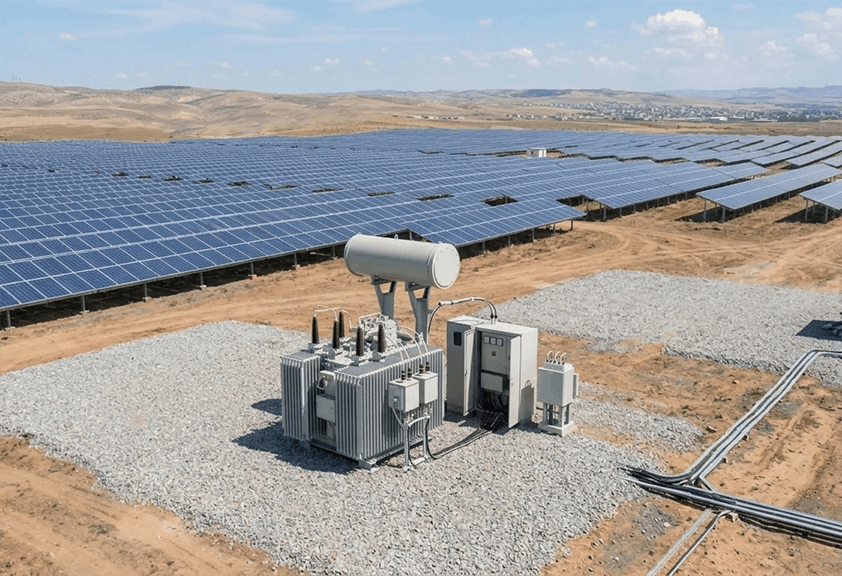
Developing megawatt-scale solar photovoltaic (PV) power plants requires a resilient power collection and grid-interconnection infrastructure whose centerpiece is the Step-Up Inverter-Duty Transformer. A critical pitfall in renewable energy projects is treating this apparatus as a standard utility distribution transformer—an oversight that leads to elevated failure rates under the demanding electrical and thermal conditions of solar farms.
Due to intermittent daily power generation, high-frequency harmonic currents generated by PWM inverters, DC offset injection, and steep daily thermal cycling, solar PV transformers endure severe dielectric, thermal, and electrodynamic stresses. Any miscalculation in specifying these units leads to localized hot spots, accelerated insulation aging, and costly plant trips.
What Is the Fundamental Difference Between a Solar PV Transformer and a Conventional Distribution Transformer?
Solar PV step-up transformers are specifically engineered to withstand daily cyclic loading (0% to 100% load swings), high harmonic currents (K-Factor design), high-frequency IGBT switching transients (dV/dt), and multi-winding magnetic decoupling (Split-LV configurations) in strict accordance with IEEE C57.159 (Guide on Transformers for Application in Distributed Photovoltaic Power Generation Systems) and the IEC 60076 series.
Technical Challenges and Structural Differences vs. Conventional Transformers
1. Daily Cyclic Loading and Thermal Mechanical Stress
Power output in a solar plant follows the daily solar irradiance curve: transformers are completely de-loaded and cold at night, ramp up rapidly after sunrise, operate at 100% rated capacity during midday peak ambient temperatures, and return to zero load at sunset. This daily thermal expansion and contraction subjects windings and clamping structures to mechanical shear stress and accelerates cellulose paper pyrolysis. Per the Arrhenius aging law, every 6°C increase above rated hot-spot temperature doubles the rate of paper insulation aging.
2. Harmonic Injection and K-Factor Design
Solar inverters convert DC power from PV arrays into AC using Pulse Width Modulation (PWM). Despite output filtering, inverter currents contain odd-order harmonics (5th, 7th, 11th, 13th, etc.) and high-frequency switching components. Because winding eddy-current losses scale with the square of the harmonic order and the square of the harmonic current amplitude, harmonic heating rises exponentially at higher frequencies.
To prevent thermal degradation, solar transformers must be designed with an appropriate K-Factor (typically K-4 to K-9), utilizing subdivided or Continuously Transposed Conductors (CTC) to minimize skin and proximity effects alongside enlarged oil cooling ducts.
3. Core Saturation Due to DC Offset
Asymmetries in IGBT switching or transient grid disturbances can inject small DC current components (from milliamperes up to a few amperes) into the low-voltage windings. Even a minor DC offset shifts the operating point on the core's B-H magnetization curve toward non-linear half-cycle saturation—sharply increasing magnetizing current, distorting waveforms, and generating stray flux heating in tank walls and structural clamping plates.
4. Multi-Winding Architecture and Isolation Impedance (Split-LV)
In utility-scale MW solar blocks, the outputs of two or more central/string inverter skids are frequently connected to a single step-up transformer using a three-winding or multi-winding configuration (Dual-LV / Split-LV: two independent low-voltage windings LV1 and LV2 coupled to a common high-voltage winding HV).
The critical engineering requirement here is complete electromagnetic decoupling between LV1 and LV2. The mutual short-circuit impedance (Isolation Impedance) between the two LV windings must be engineered in the range of 40% to 50% so that a fault or switching transient on one inverter does not induce severe voltage sag or cross-current into the second inverter.
| Technical Parameter | Conventional Grid Distribution Transformer | Utility-Scale Solar PV Transformer |
|---|---|---|
| Loading Profile | Continuous, relatively steady with gradual steps | Severe Daily Cycling (100% midday load, 0% night) |
| Current Harmonic Content | Low (THD < 5% per IEEE 519) | High (Inverter switching harmonics; requires K-Factor) |
| Core & Saturation Design | Designed near saturation knee (1.7–1.8 T) | Derated Flux Density (1.5–1.6 T) to tolerate DC Offset |
| Winding Configuration | Two-Winding (Single LV – Single HV) | Multi-Winding Split-LV (Concentric or Axial Split) |
| Power Flow Direction | Step-Down (Grid to Load) | Step-Up / Bi-directional (Inverter to MV Grid) |
| Dielectric Fluid | Standard Mineral Oil | High-Grade Mineral Oil or High-Flashpoint Natural Ester |
International Reference Standards for Solar PV Transformers
1. IEEE C57.159 (Guide on Transformers for Photovoltaic Systems)
- Cyclic Loading Formulation: Quantifies cellulose insulation aging under daily solar generation curves.
- Isolation Impedance Requirements: Mandates 40%–50% mutual impedance between split LV windings to prevent inverter cross-talk.
- DC Offset Limits: Restricts continuous DC current injection (typically < 0.5% of rated current) to prevent half-cycle core saturation.
2. IEC 60076 Series (Power Transformers)
- IEC 60076-1 (General): Nameplate ratings, tolerances, and service conditions.
- IEC 60076-2 (Temperature Rise): Strict limits on top-oil and winding hot-spot temperature rise accounting for harmonic losses.
- IEC 60076-7 (Loading Guide): Thermal modeling for cyclic loading profiles.
- IEC 60076-12 / IEEE C57.110: Capability evaluation under non-sinusoidal load currents.
3. Factory Acceptance Test (FAT) Checklist
- Partial Discharge (PD) Test (IEC 60076-3): PD level must remain strictly below 100 pC to verify electrostatic shield and turn-to-turn insulation integrity against high-frequency IGBT voltage spikes.
- Lightning Impulse Test: Verifies BIL withstand for exposed outdoor solar arrays.
- Sweep Frequency Response Analysis (SFRA): Establishes baseline mechanical winding geometry against cyclic electrodynamic forces.
- Temperature Rise Test: Conducted with total losses (including harmonic eddy-current losses) to verify cooling performance.
Step-by-Step Engineering Selection & Sizing Guide
1. Calculating True Apparent Power Rating (kVA / MVA)
A solar transformer's nameplate kVA rating must account for inverter DC/AC oversizing plus four critical derating factors:
- Power Factor (PF): Reactive power capability required at the Point of Common Coupling (typically 0.90 to 0.95).
- Ambient Temperature Derating: Desert solar sites frequently exceed standard 40°C ambient limits.
- Altitude Derating: Reduced air density at elevations above 1,000 meters above sea level lowers convective cooling efficiency.
- Harmonic Derating Factor: Thermal allowance for inverter harmonic spectrum.
2. Concentric Split-LV Winding Geometry
When connecting two inverters to a Dual-LV transformer, Concentric Split winding arrangement (LV1 inner, HV middle, LV2 outer) provides superior impedance symmetry, electromagnetic decoupling, and short-circuit mechanical strength compared to axial top/bottom stacked arrangements.
| Technical Parameter | Standard Specification | Engineering Reference / Purpose |
|---|---|---|
| Typical Unit Rating | 2,500 kVA / 3,150 kVA / 5,000 kVA | Matched to Central/String Inverter Skid Blocks |
| Winding Vector Group | Three-Winding Split-LV (Dy11y11) | IEEE C57.159 Compliance |
| Short-Circuit Impedance (HV–LV) | 6% to 8% | Grid Fault Current Limitation |
| Isolation Impedance (LV1–LV2) | 40% to 50% | Prevents Inverter Cross-Currents |
| Dielectric Fluid | Natural Ester / High-Grade Mineral Oil | IEC 61099 / High Flash Point |
| Cooling Class | ONAN / KNAN (with ONAF/KNAF provision) | Midday Peak Thermal Stability |
| Solid Insulation Class | Thermally Upgraded Paper / Aramid Reinforced | High Hot-Spot Thermal Withstand |
Operation, Predictive Maintenance (O&M), and Online Monitoring
- Fiber-Optic Winding Hot-Spot Monitoring: Direct fiber-optic temperature probes embedded inside LV/HV windings transmit real-time hot-spot data to plant SCADA.
- Online Dissolved Gas Analysis (Online DGA): Continuously tracks hydrogen (H₂), methane (CH₄), ethylene (C₂H₄), and ethane (C₂H₆) to detect partial discharge or core/winding overheating early.
- Predictive O&M Schedule: Includes 6-month Karl Fischer oil moisture testing, monthly infrared (IR) thermography of bushings and terminations, continuous HFCT partial discharge monitoring, and annual oil acidity/dielectric testing.
Frequently Asked Questions (FAQ)
1. Why can't standard distribution transformers be used in solar power plants?
Conventional transformers are designed for steady sinusoidal loads; using them in PV plants causes premature insulation failure due to inverter harmonics, cyclic thermal expansion stress, and DC offset core saturation.
2. What K-Factor rating is recommended for solar PV transformers?
Depending on inverter topology and filtering, a K-Factor between K-4 and K-9 is typically specified to accommodate high-frequency harmonic eddy-current losses.
3. Why is Concentric Split winding preferred over Axial Split?
Concentric Split windings provide balanced impedance and high magnetic decoupling (40%–50% isolation impedance), preventing faults or transients on one inverter from disturbing the second inverter.
4. What is the role of Natural Ester oil in solar transformers?
Natural esters offer a fire point above 300°C, 100% biodegradability, and higher moisture tolerance that extends cellulose paper life under severe daily thermal cycling.
5. What is the permissible Partial Discharge (PD) limit for solar transformers?
Per IEC 60076-3, partial discharge must be less than 100 pC at test voltage to ensure insulation resilience against high-frequency IGBT switching surges.