Introduction to Transformer Types and Their Applications
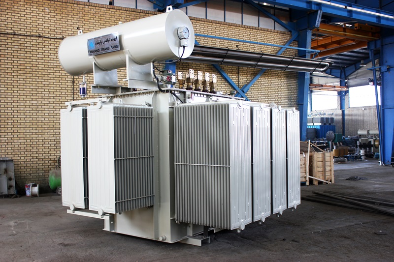
Transformers are foundational components of modern electrical power systems, playing a decisive role in power generation, long-distance transmission, and localized distribution. By stepping alternating voltage levels up or down with high efficiency, transformers enable electrical energy to be transmitted over hundreds of kilometers with minimal line loss and safely delivered to industrial, commercial, and residential consumers. In this comprehensive article, we explore the history, operating principles, structural components, loss mechanisms, and classifications of electrical transformers.
History and Evolution of Transformers
The practical development of electrical transformers dates back to the 1880s, when pioneers such as Ottó Bláthy, Miksa Déri, and Károly Zipernowsky in Hungary (at the Ganz Works), followed by William Stanley, Nikola Tesla, and George Westinghouse, harnessed Faraday's law of electromagnetic induction to build the first alternating-current (AC) distribution transformers. Throughout the 20th and 21st centuries, breakthroughs in cold-rolled grain-oriented silicon steel (CRGO), high-grade dielectric fluids, vacuum processing, and computer-aided electromagnetic design transformed these devices into ultra-efficient cornerstones of global power grids.
What Is a Transformer?
A transformer is a static electromagnetic apparatus that transfers electrical energy between two or more circuits through electromagnetic induction without changing frequency. By stepping voltage up (reducing current) for transmission and stepping voltage down for end-use consumption, transformers maximize grid efficiency and operational safety.
Major Classifications of Transformers by Function
- Step-Up Transformers
- Step-Down Transformers
- Isolation Transformers
- Autotransformers
- Three-Phase Transformers
- Distribution Transformers
- Instrument Transformers (CT & PT/VT)
1. Step-Up Transformers
Installed at power generation stations, step-up transformers increase generator output voltage to high transmission levels (such as 63 kV, 132 kV, 230 kV, or 400 kV). Increasing voltage proportionally reduces line current for a given power level, drastically cutting I²R thermal line losses, minimizing voltage drop over long distances, and reducing transmission conductor cross-section costs.
2. Step-Down Transformers
Installed at transmission and distribution substations, step-down transformers reduce high transmission voltages down to medium distribution levels (20 kV / 33 kV) and finally to safe utilization voltages (400 V / 230 V) for residential appliances, commercial buildings, and industrial machinery.
3. Isolation Transformers
Designed with a 1:1 (or custom) turns ratio and full galvanic separation between primary and secondary windings, isolation transformers block DC components, suppress common-mode electromagnetic noise, protect sensitive electronic and laboratory equipment from voltage spikes, and safeguard patients and medical staff in hospital operating rooms against electric shock.
4. Autotransformers
Unlike two-winding transformers, an autotransformer uses a single continuous tapped winding shared between the primary and secondary circuits. This design reduces copper weight, physical size, and electrical losses, making autotransformers ideal for interconnecting high-voltage transmission grids with close voltage ratios, laboratory voltage regulators, and industrial motor starting—though they do not provide galvanic isolation.
5. Three-Phase Transformers
Used extensively across industrial plants, power stations, and utility distribution grids, three-phase transformers integrate three primary and three secondary windings on a common three-limb (or five-limb) magnetic core. They support versatile vector group connections—including Star-Star (Yy), Delta-Delta (Dd), Delta-Star (Dyn), and Zigzag (Yzn)—ensuring balanced load distribution and high voltage stability.
6. Distribution Transformers
Positioned near end consumers in urban neighborhoods, rural feeders, and industrial estates, distribution transformers step medium voltage down to 400 V / 230 V. They are engineered for compact installation, high 24/7 no-load efficiency, low maintenance, and long operational life.
7. Instrument Transformers (Current & Voltage Transformers)
Instrument transformers—comprising Current Transformers (CT) and Potential/Voltage Transformers (PT/VT)—isolate high-voltage power circuits from metering instruments and protective relays while scaling high currents and voltages down to standardized, safe measurement values (e.g., 1 A / 5 A and 100 V / 110 V).
Core Structural Components of a Transformer
Every transformer is built around three fundamental electromagnetic components:
- Primary Winding: Connected to the AC power source; draws alternating current to establish a time-varying magnetic flux in the core.
- Secondary Winding: Linked by the mutual magnetic flux; delivers the transformed output voltage to the load circuit.
- Laminated Magnetic Core: Constructed from stacked, insulated thin laminations of high-permeability silicon steel to guide and concentrate magnetic flux between windings with minimal reluctance and core loss.
Understanding Transformer Energy Losses
Minimizing transformer losses directly conserves energy, lowers operating costs, and extends insulation life. Losses fall into two primary categories:
- Copper (Ohmic) Losses: Resistive I²R heating generated as load current flows through primary and secondary windings; minimized by using high-conductivity electrolytic copper and optimized conductor cross-sections.
- Iron (Core) Losses: Occur continuously in the magnetic core and consist of:
- Hysteresis Losses: Caused by internal friction as magnetic domains realign with each AC cycle; minimized using high-grade grain-oriented silicon steel.
- Eddy Current Losses: Caused by circulating currents induced within conductive core steel; minimized by constructing the core from thin, surface-insulated laminations rather than solid iron.
International Standards and Future Trends
Transformer design, manufacturing, and testing are governed by strict international standards—most notably IEC 60076, IEEE C57, and ANSI—ensuring dielectric safety, short-circuit strength, and thermal reliability. Looking ahead, the rapid expansion of solar and wind renewable energy, smart grids, and electric-vehicle infrastructure is driving demand for ultra-low-loss, smart-monitored, and harmonic-resilient transformers.
Conclusion
With over half a century of engineering and manufacturing excellence, Niroo Transfo Manufacturing Co. designs and produces a complete range of distribution, power, and special transformers compliant with international standards. Contact our engineering team today for expert guidance on selecting the optimal transformer for your project.